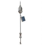
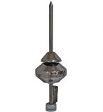
Features
- Design to meet the requirements of standards NFC17-102 and UNE-21186
- 304 stainless steel design suitable for most environments
- Available in three models to suit specific site requirements
Product Description
Protection Areas
According to NFC17-102: 2011, the standard protection radius (RP) of SI ESE is linked to ΔT (below), the protection levels I, II, III or IV (as calculated in Annex B of NFC17-102: 2011) and the height of the SI ESE above the structure to be protected (H, defined by NFC17-102: 2011 as a minimum 2 m).
Features
- Design to meet the requirements of standards NFC17-102 and UNE-21186
- 304 stainless steel design suitable for most environments
|
- Available in three models to suit specific site requirements
| Protection Level | Protection Level I
(99%, D = 20 m) |
Protection Level II
(97%, D = 30 m) |
Protection Level III
(91%, D = 45 m) |
Protection Level IV
(84%, D = 60 m) |
||||||||
| Model | SI25 | SI40 | SI60 | SI25 | SI40 | SI60 | SI25 | SI40 | SI60 | SI25 | SI40 | SI60 |
| ∆T (µs) | 25 | 40 | 60 | 25 | 40 | 60 | 25 | 40 | 60 | 25 | 40 | 60 |
| h (m) | RP (m) Protection Radius | |||||||||||
| 2 | 17 | 23 | 32 | 19 | 26 | 34 | 23 | 30 | 40 | 26 | 34 | 44 |
| 3 | 25 | 35 | 48 | 26 | 39 | 52 | 34 | 45 | 59 | 39 | 50 | 65 |
| 4 | 34 | 46 | 64 | 39 | 52 | 68 | 46 | 60 | 78 | 52 | 67 | 87 |
| 5 | 42 | 58 | 79 | 49 | 65 | 86 | 57 | 75 | 97 | 65 | 83 | 107 |
| 6 | 43 | 59 | 79 | 49 | 66 | 86 | 58 | 76 | 97 | 66 | 84 | 107 |
| 7 | 44 | 59 | 79 | 50 | 66 | 87 | 59 | 76 | 98 | 67 | 85 | 108 |
| 8 | 44 | 59 | 79 | 51 | 67 | 87 | 60 | 77 | 99 | 68 | 86 | 108 |
Where h≥5 m, then RP can be calculated from RP(h) = √2rh-h2+Δ (2r+Δ) for h≥5m
Where 2 m ≤ h ≤ 5 m, then RP can be calculated from RP = h x RP (5) / 5
RP (h) (m) is the protection radius at a given height h h (m) is the height of the SI ESE tip over the
horizontal plane through the furthest point of the object to be protected
r (m) 20 m for protection level I 30 m for protection level II 45 m for protection level III 60 m for protection level IV
Δ (m) Δ = ΔT x 106
Working Principles
During thunderstorm conditions when the lightning down-leader is approaching ground level, an upward leader may be created by any conductive surface. In the case of a passive lightning rod, the upward leader propagates only after a long period of charge reorganization. In the case of SI ESE, the initiation time of an upward leader is greatly reduced. The SI ESE generates controlled magnitude and frequency pulses at the tip of the terminal during high static fields characteristic prior to a lightning discharge. This enables the creation of an upward leader from the terminal that propagates towards the downward leader coming from the thundercloud.
ER-BASE-SS ER-BASE-SS
System Requirements
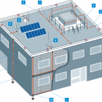
The design and installation of the terminals should be completed in compliance with the requirements of the French Standard NF C 17-102. In addition to terminal placement requirements, the standard requires a minimum of two paths to ground per terminal for non-isolated conductor systems. A down conductor cross-sectional area of ≥50 mm2 is specified. The down conductors are to be secured at three points per meter with equipotential bonding made to nearby metallic items.
Each down conductor requires a test clamp and dedicated earth system of 10 ohms or less. The lightning protection ground should be connected to the main building ground and any nearby buried metallic items. The NF C 17-102 and similar ESE standards requirements for inspection and testing range from each year to every four years dependent upon location and protection level selected.


